Introduction
Most of the designs on the web for 2.4 GHz omni antenna seem to involve brass tubing and lmr-400 cable, none of which are readily available to me. I then found a coax only design for 444Mhz that was based on the same idea. The only reasonable cable I could get my hands on was RG-213 from Maplin. By scaling the 444Mhz design up to 2.4 Ghz and using RG-213 I thought I'd have a go. In order to get about 6db gain from the antenna, it would need 8 sectors, with a 1/4 wave section at the top and a fly-lead with N-connector at the bottom. It should take about 2-3 hours to build an antenna using this design, but don't worry if it takes longer, you will get quicker, especially as you only need to make the jig once.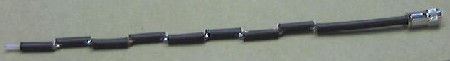
Each sector of the antenna needs to be a 1/2 wavelength long multiplied by the velocity factor of the cable. The velocity factor of RG-213 is 0.66 . If you decide to use different cable (such as LMR-400) then you need to get the velocity factor of that cable (which will be different), and recalculate all the dimensions.
                  V * C    0.66 * 299792458
1/2 wavelength = ------ = ---------------- = 0.0405m = 40.5mm
                  2 * F     2 * 2441000000

V = Velocity Factor   of  RG213  = 0.66
C = speed of light = 299792458
F = Frequency of Signal = 2441000000 (middle of 2.4ghz range)
The 1/4 wave element is not adjusted by the Velocity factor, as it is in the open, so works out at just 31mm long giving a total antenna length of 355mm + fly-lead. (Thanks to Oscar for correcting me of this.)
Getting the parts
All of the parts are available cheaply from either Maplin and any diy shop.
- 1m RG-213U cable (available by the meter from Maplin). This is enough for 2 antenna. Buy more for whatever flylead length you want.
- N connectors, Depending on what you want to connect to , use either male or female connectors, and inline or bulkhead. Remember inline connectors need to fit 10mm diameter RG-213 cable
- 20mm pvc conduit (available from any diy store) Has a 20mm inside diameter, and 22mm outside.
- 22mm pipe clips (depending on how you want to mount the antenna), pipe clips make it easy to mount and unmount, or use the proper conduit brackets (but they seem a little expensive).
You don't need any special tools
- mm rule for measuring !
- junior hacksaw
- stanley knife
- pliers
- standard soldering iron (don't need a heavy duty one) and solder
- off cuts of wood to make a jig to aid soldering
- bench or vice to hold cable while you cut it
Cut the pieces
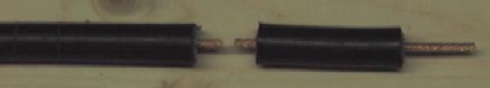
After much trial and error, I found that the neatest way to cut the cable is actually with a junior hacksaw. It gives a much cleaner finish than wirecutters. Each sector consists of a short length of RG-213 cable, with the central core sticking out each end.
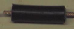
When building the antenna, the exact length of each piece of RG-213 is not that important, it is the overall length of each sector that counts. I found that cutting the cable to 37mm with 6mm of core sticking out each end, gets enough overlap to easily solder the segments together. If you allow 1mm for the width of the hacksaw when cutting the sectors apart, it means you need 37 +6 +6 +1 = 50mm of cable for each sector making 8sectors + 1/4wave section come to 420 mm of cable for the antenna + cable for the fly lead.
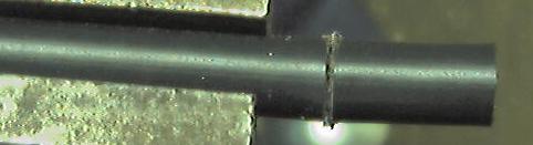
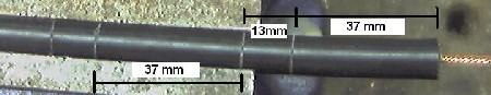
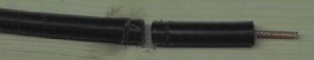
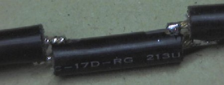
The best way to cut each sector is to make the cuts where each end of the sheathed section of the sector will be, before making the cut between each sector. The picture below shows the top 3 sections of the antenna, and the 1/4 wave section, showing the order that the cuts should be made.
The best way to make the cuts is to mark them out on the cable first. When sawing the cable it has a tendancy to deform and bend, so lightly sawing round the outside sheath first, but not cutting through, helps give a guide to the cutting for real. I use the junior hacksaw to gently saw round the cable sheath to make the mark for each section.
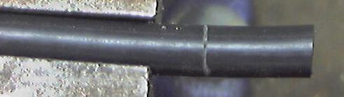
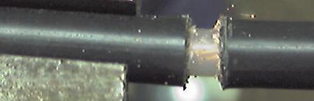
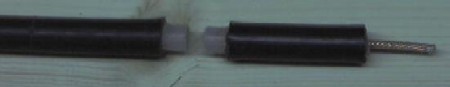
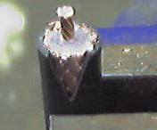
The first mark will be at 31mm from the end, which is for the 1/4 wave section at the top. Once you have made the mark, it is time to cut round the cable. You want to cut through the sheath, shielding, and just into the central insulation, but not into the central copper wires. You may need to practice a bit first, but you should be able to feel as you cut through the shielding into the central insulation. By leaving plenty of sheathed section either side of the cuts, the shielding stays in place when being cut.
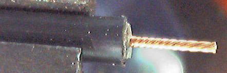
Now with pliers, gently twist off the end 31mm of sheath & shielding
This should leave the cenral insulator exposed. Using the stanley knife score round through the central insulator, but not too hard, or you will cut the central cable. Now twist off the insulation. You should be able to see the twist in the central cable through the insulation, which will show you which way to twist off the insulation, resulting in the central core twisting more tightly.
The next mark is 37mm down (68mm from end of the cable) and is the cut for other end of the sheathed section of the top sector. The next mark is 13mm down (consists of 6mm core from each sector and 1mm for cut between sectors) (81mm from end) and is the top of the sheathed section of the second sector. The next mark is 37mm down, then 13mm, then 37mm, and so on and so forth until you have each of the sheathed sections marked out.
Now you are ready to cut off the top sector from the cable. You want to cut through the whole cable at the mid point of the two cuts you have just made, that is about 43.5 mm from the end of the sheath, or 74.5 mm from the end of the cable. See position 4 in the diagram above. Just saw carefully the whole way through the cable.
Build a Jig
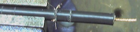
If you do not have a handy helper to hold the sectors together, then you will find it easier to make a small jig from offcuts of wood, to hold the sectors together as you solder them. The clamps on the right hand side of the picture need to be no more than 30mm long. The base board of the jig, needs to extend out to the right long enough to take the whole length of the completed antenna, as�it will need to support it during the soldering, as the antenna is not rigid enough to support itself.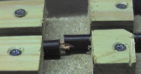
When you are readly to solder the sectors together, you need to take care , that each sector is correctly spaced. The overall length of each sector needs to be 40.5mm , measure from one end of the shielding of the sector you are adding, to the same end on the next sector, and slide the sectors together/apart until the distance is 40.5 mm. Try to get it as accurate as you can, as it affects the direction the antenna transmits in if you get it wrong. There should be a small 3mm gap between the sheaths of each sector.
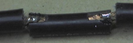
Once you have soldered each sector together, lift it up, turn it over, and move it down the clamp ready for the next sector. This results in a nice straight antenna. When soldering, remember to heat both the shielding and core so that the solder runs smoothly and fixes them together.
Once complete, test the cable with either a bulb and battery or a multimeter. The center of the fly lead should form a circuit to the 1/4 wave section, and the shield of the flylead to the shield of the top section. Now test that there are no crossed connections, by ensuring there is no circuit between the center of the flylead and the shielding of the top sector, and no circuit between the 1/4 wave section and the shielding of the flylead.
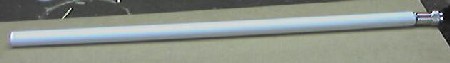
Now fix the N connector of your choice onto the end of the fly lead. The type of connector you use depends on what you want to connect to. I use inline connectors, but you could use any connector you like. Slide the antenna into a length of conduiting. It should be a snug fit, you may need to gently ease it in. Now find an old soft drink bottle top, and pop it on the top end of the antenna. Voila one complete antenna ! Securing the antenna in the conduit is best left until you are ready to mount it somewhere. You can cut 5cm slots in the bottom if the conduit, and use a jubilee clamp to grip the flylead, or drill a hole through the conduit and use a cable tie to hold the fly lead, or use a bulkhead mount connector on a botle cap, and glue it to the bottom of the conduit, or glue the flylead in place. It's up to you.
Testing
I will assume you are connecting the antenna to a wireless card in a laptop, and connecting to an accesspoint somewhere. You will need to a signal to noise meter to examine the signal strength. Most wifi cards come with software that does this. Now its time to test that the antenna actually works. This can be harder than it sounds, as unless you can remove the existing aerial from the card or ap, you can't tell it is using your new homebrew antenna. Well wrapping the existing antenna completely in 6-8 layers of tinfoil, has a dramatic reduction on signal strength, now connect the antenna, and the signal should go back up. Remember that omni antenna send out the signal horizontally, so don't test it from the room below your access point. Hopefully you should see that your new antenna actually works. There are three ways to test the gain of the new antenna
- Use spectrum analyser in a professional radio lab
- compare the gain of your new antenna, to the gain of a known antenna (Not the pcmcia card)
- Carry out an empirical range test with your new antenna
If you have a go at making this antenna, and get it working, drop me an email (address at bottom of page) and let me know how you found building it, whether you've found a simpler way, and ... be honest ... how long it took.
Problems
If you find that the antenna is not working, then try tilting it towards the AP, as if the dimensions are wrong, it tends to send the signal angled in a cone above and below the horizontal instead of horizontally. If this is the case, check the dimensions. If it still doesn't work, double check that the sectors are connected ok, and there are no crossed connections. If all else fails make sure you are not connecting it to a 60ft fly-lead as this will reduce the gain a lot.Disclaimer
I should point out now that I don't claim that the above design is fit for any purpose, and don't accept any liability for use of the design, or any antenna based on this design. If you want to build an antenna using this design, then you are responsible for ensuring that it doesn't breach any laws where you are, and is compatible with any hardware you connect it to. If in doubt, buy a commercial antenna.orignal link